LM1 calibration DX
Measuring the LM1 limit switch position as well as the optical and mechanical zero position.
Lower limit
| AbsEnc | IncEnc | SW setting |
| 1913 | -5145 | 2000 |
| 595 | -2982 | 600 |
| 606 | -4850 | 700 |
Mechanical Zero (distance was measured on the outer part of the mirror)
| AbsEnc | IncEnc | Distance mirror [mm] |
| 20602 | 2154 | 26.7 |
| 21287 | 5111 | 26.7 |
| 11046 | -765 | 26.7 |
Optical Zero
| AbsEnc | IncEnc | Distance mirror [mm] |
| 16253 | 455 | 26.45 |
| 17712 | 3715 | 26.3 |
| 23316 | 4028 | 27.8 |
Upper limit
| AbsEnc | IncEnc | SW setting |
| 47230 | 12555 | 47200 |
| 44490 | 14175 | 44400 |
| 46186 | 12961 | 46100 |
IncEnc values will change after setting the Zero position to the mechanical in SW.
Conversion factor was measured to 5000.
Interactuator range was set to 7600 (double as before, as movement is about half the way as before)
Open points:
- in case the motor moved for any reason over the limit the tripod software can not recover
- would be useful to have button to set the nominal AbsEnc position (mechZero and optZero)
- show the absolute phi and theta
We performed some preliminary checks on the
TipTiltSystemDx:
- We measured the position of the biggest aperture in the ApertureWheel: we made use of the FLAO IS and defocused the Z stage to have >5" spot on the QuadCell. Then we started to rotate the aperture wheel and recorded the fluxes of the 4 APDs.
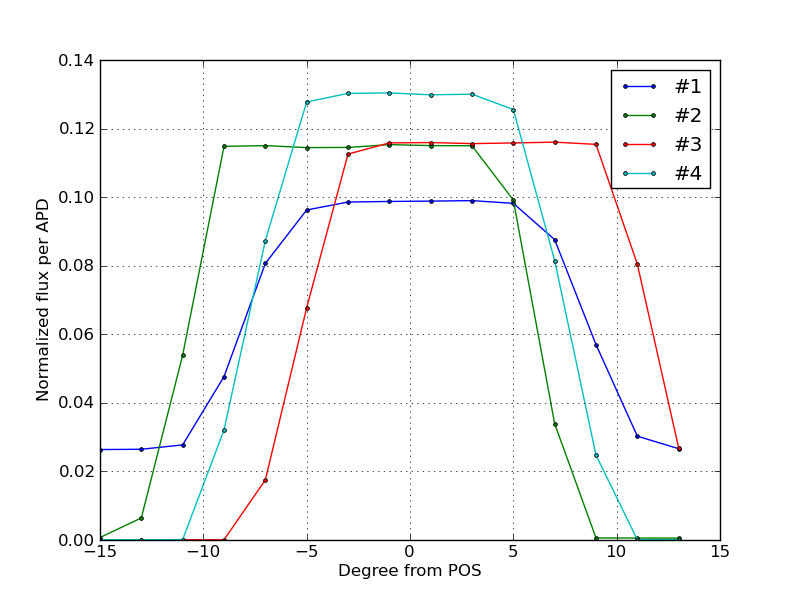
- we saw that the dichroic in the FW1 was creating 2 spots on the QC ruining the linearity measurements and also the flat acquisition
- we evaluated the geometry of the 4 APDs:
- we tryed to acquire a first flat to measure relative efficiency of the 4 channels.
- we tryed to identify the direction of the board stages axes wrt the QC itself.
