 |
|
You are here: AOWiki>ARGOSPublic Web>Commissioning>DiaryRun6>DayTime20150425 (26 Apr 2015, MarcoBonaglia)Edit Attach
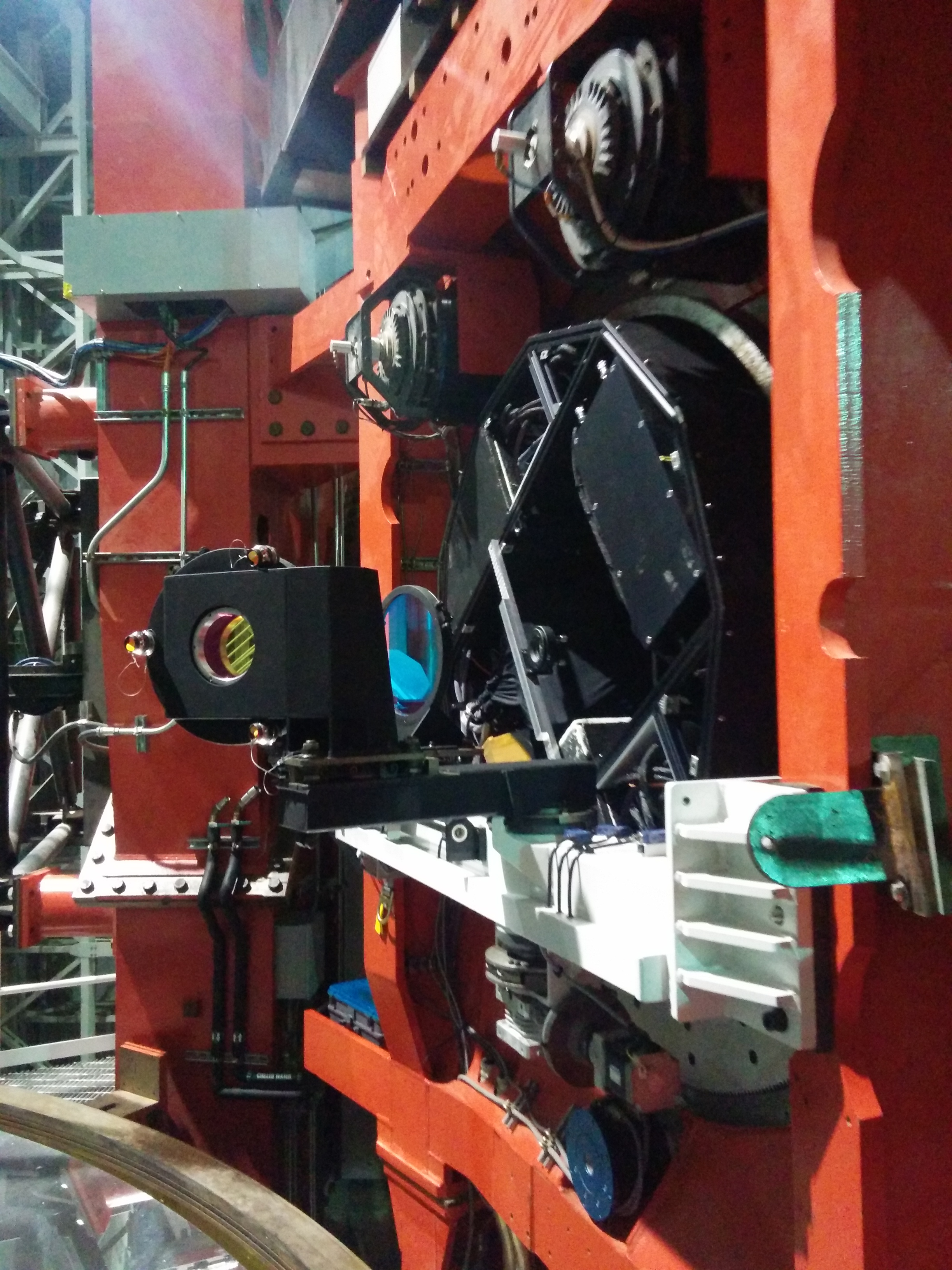
LgswDichroicSystemSX with Laser tracker
8:00: we started acquiring the telescope coordinate reference system. 3 corner cubes were mounted on the dichroic cell and another corner cube has been glued on the LUCI rotator to measure the position of its axis. After having measured 2 arcs (one on top right of the rotator flange, the other on bottom left) we compared the position of the axis with respect to the other measurements taken in 2014 and 2012. We got a discrepancy of 0.01deg in the measurements.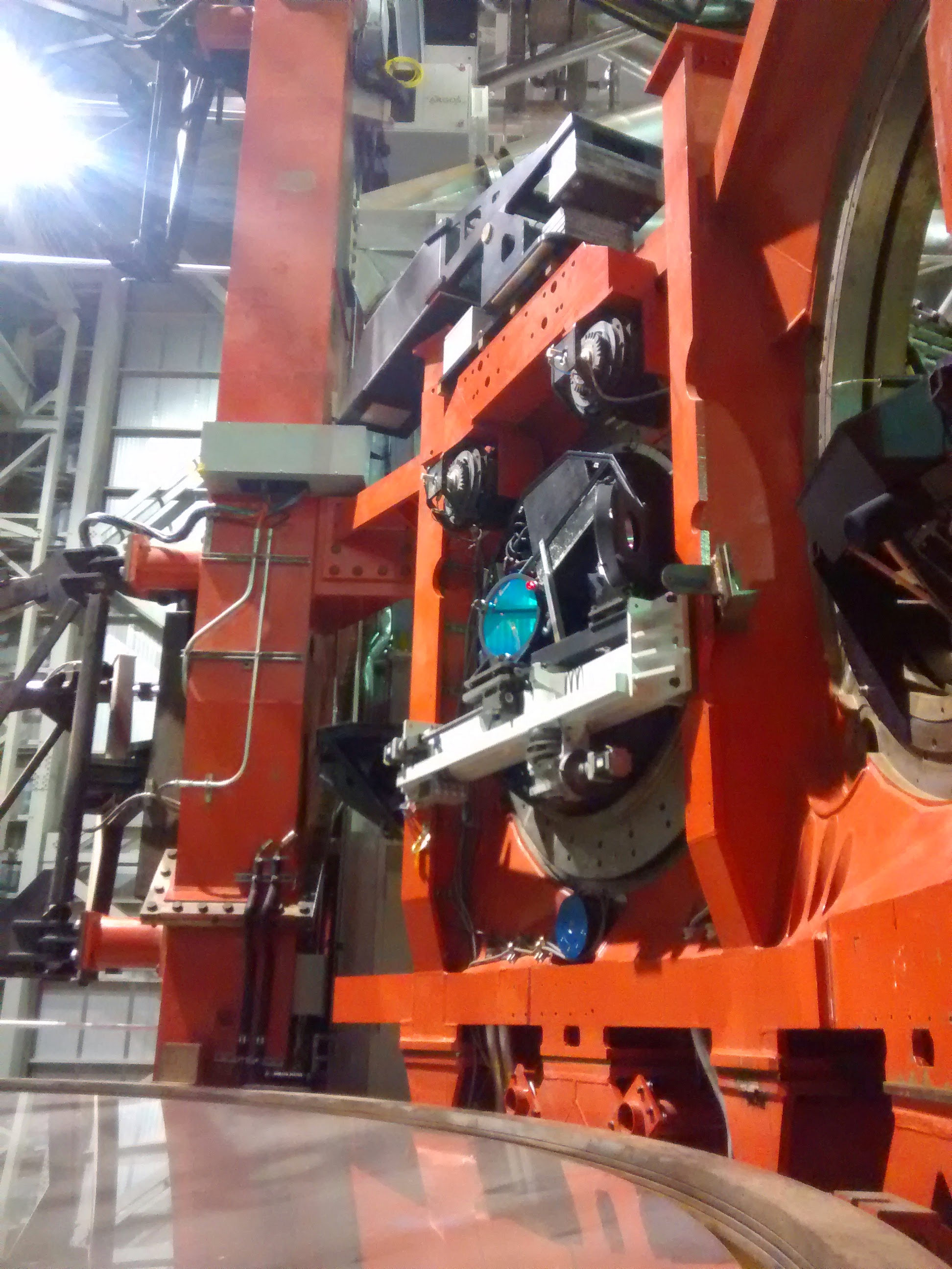 11:15: the nest we used to measure the rotator axis (glued on the rotator flange) offsets the measurements by 25.4mm. We retrieve the center of the rotator and the "AGW ralla" plane.
In the 3D measurement software we shift the telescope coordinate system in such a way to get the reference point in the ralla center.
Dichroic S1 must stay at 350mm from the ralla center, tilted by 15deg.
We draw in the software the nominal position for the dichroic S1 and then we measure the 3 points with the corner cubes: we get a tip error (vertical reflection) of 0.129deg and a tilt (error in the reflection plane) of 0.265deg.
After few iterations these errors are lowered to 0.003deg and 0.008deg respectively.
13:30: concluded the dichroic alignment we move the corner cubes on the back of the fold mirror cell. To do this we need to remove the small brackets that hold the rigid cover. The normal to the fold mirror plane is tilted by 36.25deg with respect to the dichroic normal. We shift the coordinate system from the dichroic S1 to the fold mirror S1 center.
The initial tip and tilt errors for the mirror are: 0.016deg and 0.229deg. After one iteration we had been able to get: 0.1deg of tip error and 0.05deg of tilt error. The rise in the tip error is due to the bottom nest that cannot be placed in contact with the back mirror cell because it collides with a nut.
11:15: the nest we used to measure the rotator axis (glued on the rotator flange) offsets the measurements by 25.4mm. We retrieve the center of the rotator and the "AGW ralla" plane.
In the 3D measurement software we shift the telescope coordinate system in such a way to get the reference point in the ralla center.
Dichroic S1 must stay at 350mm from the ralla center, tilted by 15deg.
We draw in the software the nominal position for the dichroic S1 and then we measure the 3 points with the corner cubes: we get a tip error (vertical reflection) of 0.129deg and a tilt (error in the reflection plane) of 0.265deg.
After few iterations these errors are lowered to 0.003deg and 0.008deg respectively.
13:30: concluded the dichroic alignment we move the corner cubes on the back of the fold mirror cell. To do this we need to remove the small brackets that hold the rigid cover. The normal to the fold mirror plane is tilted by 36.25deg with respect to the dichroic normal. We shift the coordinate system from the dichroic S1 to the fold mirror S1 center.
The initial tip and tilt errors for the mirror are: 0.016deg and 0.229deg. After one iteration we had been able to get: 0.1deg of tip error and 0.05deg of tilt error. The rise in the tip error is due to the bottom nest that cannot be placed in contact with the back mirror cell because it collides with a nut.
Edit | Attach | Print version | History: r1 | Backlinks | View wiki text | Edit wiki text | More topic actions
Topic revision: r1 - 26 Apr 2015, MarcoBonaglia
Ideas, requests, problems regarding AOWiki? Send feedback