 |
|
You are here: AOWiki>ARGOSPublic Web>ArgosDeviceList>BCU (19 May 2016, MarcoBonaglia)Edit Attach
List of devices of this kind
| Name | Serial Number | Location |
|---|---|---|
| BCU #1 | 0001 | LgswRack2 |
| BCU #2 | 0002 | LgswRack1 |
| BCU #3 | 0003 | LBT |
- BCU #1 a.k.a. Heidelberg-BCU (the one originally in HD for SW development)
- BCU #2 a.k.a. ADC-BCU (the first one with the ADC board received in Florence with the DX rack)
Documentation
- LBT-MIC-TRE-00910-0001_Rev3.pdf: ARGOS BCU mini-crate system design from Mario 9 apr 2014
- LBT-MIC-TRE-00910-0001_RevDraft-1.doc: ARGOS BCU mini-crate system design - Old
- Requirements_for_ARGOS_BCU_v1.3.pdf: Requirements for the ARGOS BCU v1.3
- ARGOS_CodesMemMap_v4.xls: Memory address map. From Mario 9 apr 2014
- ARGOS_CodesMemMap_v2.xls: Address Map of BCU. From Mario 16 Apr 2012. Obsolete
- CSA329.1_-_CSD309_-_AdOpt_DSP_8ch_ADC_Board_1_1_-_SCH.pdf: Electronic schematics of ADC board. Received by Roberto Biasi Mar 12, 2013
Firmware database
- BCULogic_11_65.rbf: Logic to be flashed into BCU FPGA. From Mario, 19 Jul, 2013
- BCULogic_11_66.rbf: Logic to be flashed into BCU FPGA. From Mario, 19-20 Mar, 2013
- BCULogic_11_67.rbf: Logic to be flashed into BCU FPGA. From Mario, 19-20 Mar, 2013
- BCULogic_11_68.rbf: Logic to be flashed into BCU FPGA. From Mario 19 Nov 2013
- BCULogic_11_69.rbf: Logic to be flashed into BCU FPGA. From Mario 19 Nov 2013
- BCULogic_11_70.rbf: Logic to be flashed into BCU FPGA. From Mario on 04 Feb 2014 (Same version on 03 Feb is bugged). Fixed Fastlink issue.
- BCULogic_11_71.rbf: FLAO-ARGOS-Switch fastlink issues. From Mario 15 apr 2014
- DSPLogic_8_46.rbf: Logic to be flashed into ADC (DSP00) FPGA. It allows enabling/disabling of ADCs. From Mario, 15 apr 2013
- DSPLogic_8_45.rbf: Logic to be flashed into ADC (DSP00) FPGA. From Mario, 19 Jul, 2013
- DSPLogic_8_44.rbf: Logic to be flashed into ADC (DSP00) FPGA. From Mario, 19-20 Mar, 2013
- DSPLogic_8_43.rbf: Logic to be flashed into ADC (DSP00) FPGA. From Mario, 19-20 Mar, 2013
- HVCLogic_2_01.rbf: Logic to be flashed into HVC (DPS02, DSP04). From Mario, 19 Jul, 2013
- DSPNios_4_02_0020.bin: Nios HVC (DPS02, DSP04). From Mario, 19 Jul, 2013
- DSPNios_5_06_0040.bin: Nios ADC (DSP00). From Mario, 19 Jul, 2013
- BCUNios_5_07_0046.bin: Nios BCU FPGA. From Mario, 19 Jul, 2013
- BCUNios_5_08_0046_readFromFlash.bin: Nios BCU FPGA. Read from Flash with 'readFlash.m', Gilles, 11 May, 2014
- BCUNios_5_09_0046.bin-NO: Nios BCU FPGA. From Mario, 11 May, 2014. ParamSelector issue, Currently not working!
- BCUNios_5_09_0046.bin: Nios BCU FPGA. From Mario to Alfio about 25 May, 2014. ParamSelector issue fixed (TBC). Use with BCU6.10 and DSP2.05
Maintenance
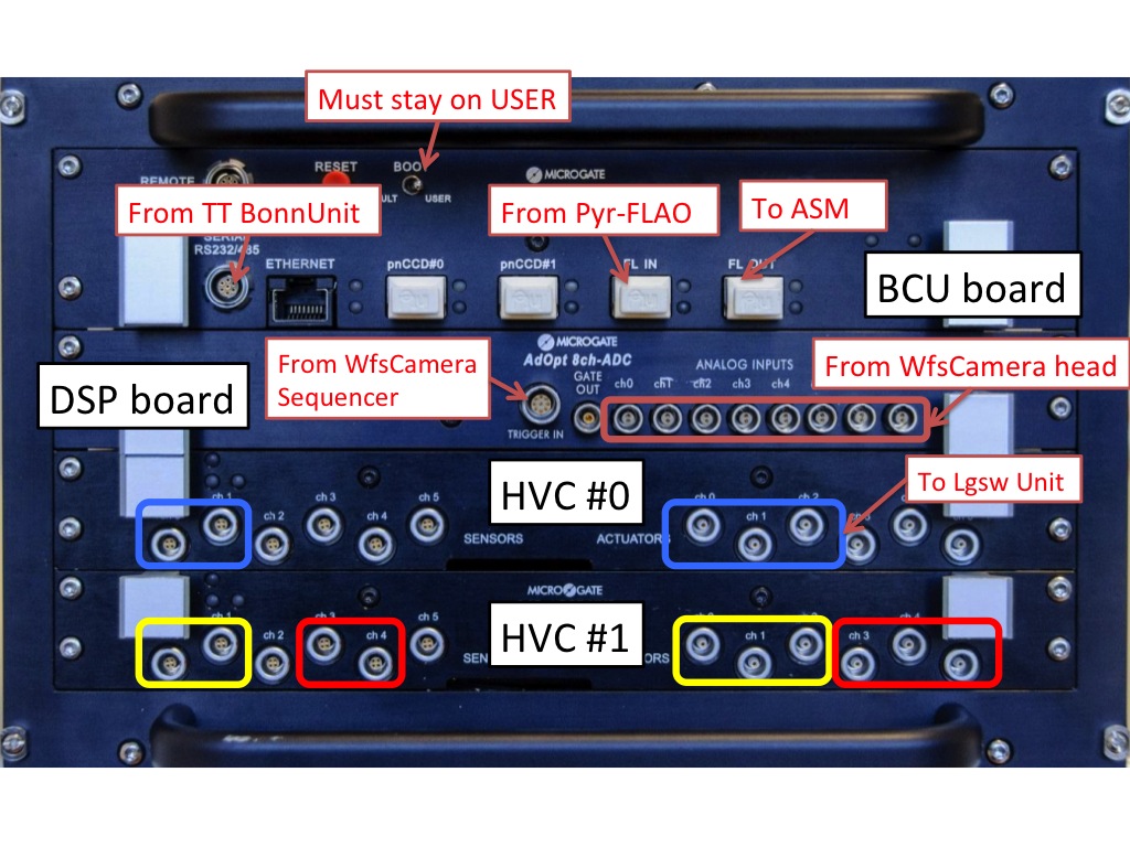
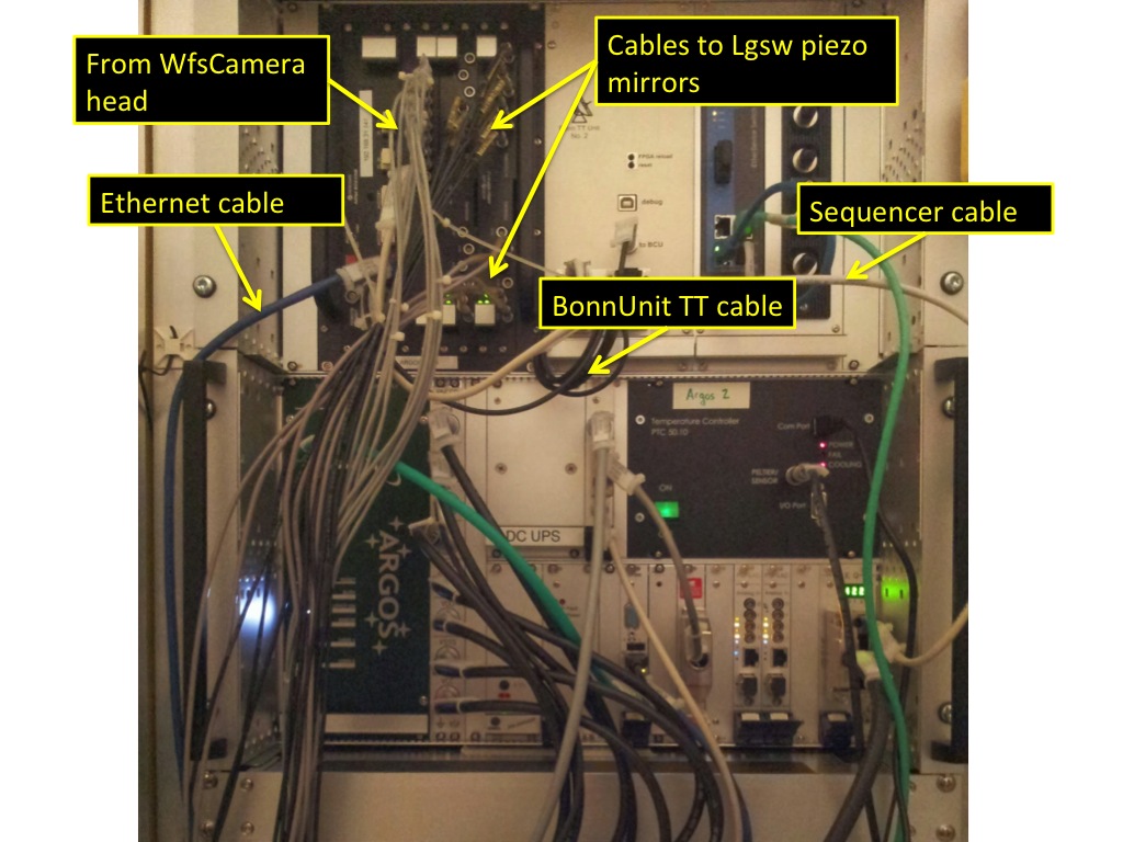
The BCU is installed in the ElectronicRackLgsw and it is connected to several devices:- to the WfsCamera head via 8 thin LEMO cables on the DSP board
- to the WfsCamera electronic via a sequencer cable
- to the 3 PiezoPIS334 used for jitter stabilization in the LgswUnit via 5 LEMOs cable each connected to the 2 HVC boards
- to the ethernet switch in the LaserSupplyRack
- to the ASM via the optical fiber connected to the FastLink "FL output"
- to the TipTiltComputer (aka Bonn unit) via a serial cable on the BCU board
- to the FLAO pyramid WFS can send slopes to the ARGOS BCU using the Fastlkink "FL input"
Power Off the BCU
- Make sure the BCU is correctly connected and the ElectronicRackLgsw is on.
- From the LabGUI, select the "Rack I/O" tab
- Click ON on "BCU Reset" to power OFF the BCU
- In the LabGUI select the BCU tab and check that the connection LED is red
Power On the BCU
- Make sure the BCU is correctly connected and the ElectronicRackLgsw is on.
- From the LabGUI, select the "Rack I/O" tab
- Click OFF on "BCU Reset" to power ON the BCU
- In the LabGUI select the BCU tab and check that the connection LED turns green. It typically takes <30s.
Remove a BCU from the ElectronicRackLgsw
- Power off the BCU using the remote command. LEDs should be all off.
- Take a picture of current cabling.
- Unplug all cables paying attention that they are all labelled.
- Unscrew the BCU from the rack (four small cross-screws on each corner).
- Take partially out smoothly the BCU and reach the power switch on the back of the BCU to switch it off.
- Disconnect the power plug on the back of the BCU. It is the only cable on the back of the BCU.
- Fully remove the BCU from the rack.
- Store the BCU in ArgosCabinet0
- Update the corresponding twiki page and notify Lorenzo.
Install a BCU in the ElectronicRackLgsw
- [Only if you need to change the IP address] It may be easier to do this using a laptop. If it is already on the correct subnet you can use the VirtualBox and its EngPanel.
- Make sure the remote power to the BCU power plug is off by checking on the remote command.
- Make sure the power switch on the back of the BCU is set to ON.
- Connect the power plug on the back of the BCU.
- Insert the BCU in the rack following the red rails.
- Screw the BCU to the rack (four small cross-screws on each corner).
- Plug all cables paying attention to labels.
- Take a picture of current cabling.
- Power on the BCU using the remote command. LEDs should be all on.
- Double check that the optical fiber is connected to the FL output; a single blue LED is on if there is already a physical link (the selected ASM input port is the ARGOS's one)
- Update the corresponding twiki page and notify Lorenzo.
Firmware configuration
Use the EngPanel to:- set the IP address
- upload a new firmware version
- read diagnostic parameters
- check configuration
Read power supply voltage on BCU board
Roberto provided 2 pages showing HowToAdjustBcuPowerSupply.Connect fastlink to FLAO and ASM
GustavoRahmer maintains informations about HowToInstallARGOSFiberSplitter
Edit | Attach | Print version | History: r21 < r20 < r19 < r18 | Backlinks | View wiki text | Edit wiki text | More topic actions
Topic revision: r21 - 19 May 2016, MarcoBonaglia
Ideas, requests, problems regarding AOWiki? Send feedback